
- #PROTEUS 8 ROTARY ENCODER HOW TO#
- #PROTEUS 8 ROTARY ENCODER FULL#
- #PROTEUS 8 ROTARY ENCODER DOWNLOAD#
A side effect of debounce is that fast rotations can cause steps to be skipped. Other algorithms emit spurious output with switch bounce, but this one will simply flip between sub-states until the bounce settles, then continue along the state machine. The biggest advantage of using a state machine over other algorithms is that this has inherent debounce built in. If an invalid state happens (for example we go from '0-1' straight to '1-0'), the state machine resets to the start until 0-0 and the next valid codes occur. In Rotary.h, uncomment #define HALF_STEP to enable half-step mode. This might be useful for some encoders where you want to detect all positions. This just emits an event at both the 0-0 and 1-1 positions. It's also possible to use 'half-step' mode. At the final 0-0, it returns a value indicating a step in one direction or the other.
#PROTEUS 8 ROTARY ENCODER FULL#
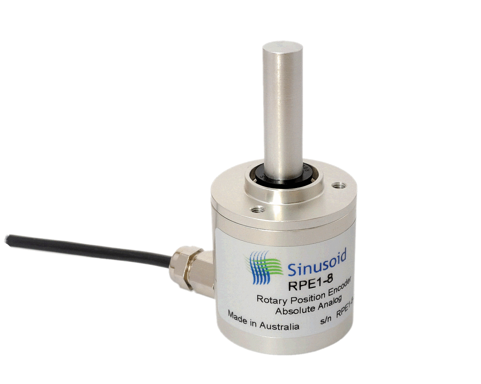
Every time the output code changes, it follows state, until finally a full steps worth of code is received (in the correct order). To decode this, we use a simple state machine. Finally at the end of the step, both bits return to 0.ĭetecting the direction is easy - the table simply goes in the other direction (read up instead of down).Then Bit1 goes low, but Bit2 stays high.Then both bits are high, halfway through the step.From an initial 0 - 0, Bit1 goes high, Bit0 stays low.The following is the typical sequence of code on the output when moving from one step to the next:įrom this table, we can see that when moving from one 'click' to the next, there are 4 changes in the output code. There are 3 pins used for the rotary encoding - one common and two 'bit' pins. Every step in the output (often accompanied by a physical 'click') generates a specific sequence of output codes on the pins. r.begin(false, true) disables the internal pull-ups and flips the pin logic for use with external pull-downsĪ typical mechanical rotary encoder emits a two bit gray code on 3 output pins.r.begin(false) disables the Arduino's internal weak pull-ups for the given pins and configures the rotary for use with external pull-ups.r.begin() enables the Arduino's internal weak pull-ups for the rotary's pins.

Note: Resistor usage is specified through void begin(bool internalPullup=true, bool flipLogicForPulldown=false). So for example Rotary.h will be in Arduino\libraries\Rotary\Rotary.h.
#PROTEUS 8 ROTARY ENCODER DOWNLOAD#
Download and unzip to Arduino\libraries\Rotary.Supports use with pull-up (default) and pull-down resistors.Counts full-steps (default) or half-steps.Checks for valid state changes for more robust counting / noise immunity.Correctly handles direction changes mid-step.Debounce handling with support for high rotation speeds.This is a repackaged version of Ben Buxton's excellent rotary library organized for the Arduino 1.x IDE, keyword highlighting, polling example, Arduino library capitalization conventions. DC motor control with PIC16F877A and rotary encoder CCS C (result = DIR_CW ? "Right" : "Left") PORTB interrupt on change (IOC) is used to detect the movement of the rotary encoder. CLK and DT pins are connected to RB4 and RB5 respectively. The rotary encoder push button terminal is connected to pin RB3, with this button we can change the direction of rotation of the motor. The active PWM pin decides the motor direction of rotation (one at a time, the other output is logic 0). By setting both modules in PWM mode we get 2 PWM signals with the same frequency on pins RC2 (PWM1) and RC1 (PWM2), at any time there is only 1 active PWM, this allows us to control the direction as well as the speed by varying the duty cycle of the active PWM signal. The PIC16F877A microcontroller has two CCP modules, CCP1 and CCP2 (CCP: Capture/Compare/PWM). Pin IN1 and pin IN2 are the control pins where: IN1 The L293D is supplied with 2 different sources, the first one (VCC1) is +5V, and the 2nd one (VCC2) is +12V which is the same as motor nominal voltage. The rotary encoder generates (when rotating) two square waves on pins A (CLK) and B (DT) with 90° out of phase as shown in the figure below:Īs shown in the figure, the rotary encoder has 4 phases: With the three pull-up resistors, the normal state of each terminal is logic high. The rotary encoder has 5 pins: GND, + (+5V or 3.3V), SW (push button), DT (pin B) and CLK (pin A).Īs an addition to the rotary encoder there is a push button and three pull up resistors for pins SW, DT and CLK of 10K ohm. In this example I used the rotary encoder shown in the image below:
#PROTEUS 8 ROTARY ENCODER HOW TO#
Previously I posted an example shows how to control a DC motor speed and direction using PIC16F877A and a potentiometer, example link is below:ĭC motor control with PIC16F877A and L293D – Proteus simulation This example shows how to use a rotary encoder with PIC16F877A microcontroller in order to control the speed and direction of rotation of a DC motor.


 0 kommentar(er)
